|
To place the timing lines on your form, click Timing Lines tool button  to open the Timing
Marks dialog box. to open the Timing
Marks dialog box.
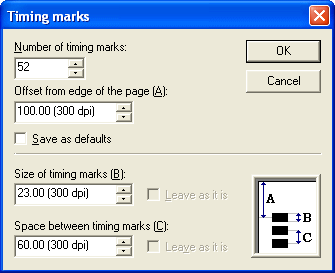
The default timing mark values are taken from your
grid definition, but you can enter custom values for:
- The Number of Timing marks that appear on the
edge of your form
- The distance between the paper edge and the
center of the first timing mark (value A on the following diagram)
- The height of each mark (value B)
- The space between mark centers (value C)

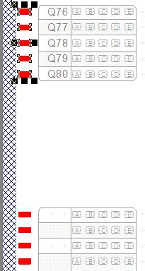
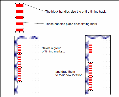
When you click OK, each timing mark appears in red
with editing handles at its corners, and the entire line has black
handles. This means you can change the position of the timing marks,
and move them around your page so you can accurately place response
grids.
The black handles that appear around all the
timing marks allow you to "drag" the start of the timing line on the
page. You can select a sub-set of timing marks by running the marquee
around them, those will be given handles and can now be dragged.
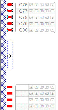
Finally, you can use Crtl+M to move a selected set of timing marks and
clone them. These are the three steps involved:
Select and hold down Ctrl and M to drag and
duplicate that set of timing marks (as shown).
| Selection |
Holding down Ctrl + M and dragging with
mouse |
Let go of mouse |
 |
 |
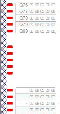 |
To change the
placement of the channels, select marks to shift, and drag
them with the
mouse to their new location.
To select new values for a set of timing marks,
select the marks to change and press Mouse Right. This short menu
appears (in this case showing Sizes
selected).
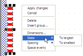
Select Dimensions
to open the Timing Marks
dialog box and enter Offset
from paper edge, Size
of timing marks and Space
between timing marks.
|