| |
|
| Prepare Your Workspace |
 |
|
|
| Paper Size |
|
Select a paper size for your printer. To
change a form's page size, select one of the standard page sizes
available in the list.
|
|
| Top
|
| Page Orientation |
|
Portrait (vertical page) and landscape
(horizontal page) orientations are available with different timing
track placements.
Orientation should be chosen to reduce skew
on laser printed forms and/or to reduce sheet damage where
the sheet enters the scanner on commercially printer forms.
Laser printed forms
should generally have timing marks bottom or right for normal use,
where the objective is to have response positions closer to the timing
marks, thus reducing skew.
Booklet Forms should
be printed to avoid damage on the timing mark entering the scanner
first.
Your scanner may include
restrictions on Form ID marks (generally best on the first line into
the scanner) and for paper folds across the short dimension (generally
use a large timing mark and IGNORE erroneous marks in this area). |
|
| Top
|
| Double Sided Printing (Duplex) |
|
Select the type of double sided printing
(duplexing) to be used for the form. Choose from simplex (one sided
printing), flip on long edge or flip on short edge.
When Duplex printing is selected the
Front  and Back and Back  buttons on the toolbar become available. Click the buttons to move
from one side to the other.
buttons on the toolbar become available. Click the buttons to move
from one side to the other.

- Number 1 indicates the front of the form
- Number 2 indicates the back of the form
- The arrows indicate how the form is fed
through the scanner, for a left to right scanner.
Note: Many laser
printers induce skew on the reverse side, please check
your laser's performance before using double sided pages for OMR. For
from-Image forms, this does not matter as the form is normally
de-skewed electronically.
|
|
| Top
|
| Tombstones |
|
Tombstones are rectangles in the corner of
Scan-from-Image forms. Press
 at bottom
if you require
a form where the data is scanned from an image rather than being
defined by OMR marks. at bottom
if you require
a form where the data is scanned from an image rather than being
defined by OMR marks.
This
screen appears on which you define the tombstone height and width and
whether tombstones are printed in each of the four corners. The offsets
are for the top left Tombstone and repeat for all of the others, from
the edge of the page.
|
|
| Top
|
| Grid |
|
The Response Grid is a set of possible
positions, aligned with the timing track, where the reader scans form
responses. On your form design, the response grid is shown as red
cross-hairs.
The position of the timing marks defines one dimension of the grid, the
other is defined by the read head of the OMR scanning the form.
To change the response grid, select a
compatible grid for your OMR reader, or create a custom definition.
Note: Ensure you select the timing mark spacing compatible with your
OMR scanner.
|
|
| Top
|
| Custom Grid Definition |
|
To Create a Custom Grid definition:
- Click Page Setup in the File menu.
- Click the Finder
 button next to the Grid
list to create a custom grid definition. button next to the Grid
list to create a custom grid definition.
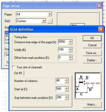
To change the position of the timing track,
set the following dimension (in 1/1200 per inch measurements):
- The distance from the edge of the page to
the outer edge of the timing mark (value A on the
dialog box diagram).
- The width of the timing mark (value B)
- The offset of the center of the possible
response positions from the center of the timing marks (value E).
The following settings define a channel bank:
- The number of columns in the channel.
This is the maximum number of response positions along each timing line.
- The distance from the paper edge to the
middle of the first column (value C) in the dialog
box diagram).
- The distance between response positions
in the column (value D).
If your OMR supports two channel banks, you
can create banks by clicking Two sets of channels
and setting up the second bank.
To change the shape and size of the timing
marks, click the Marks button and change the required settings.
- Minimum size of the mark and Maximum size
of the mark set height threshold for all timing marks.
- The minimum space between marks sets the
smallest distance required between marks.
|
|
| Top
|
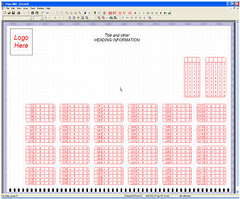
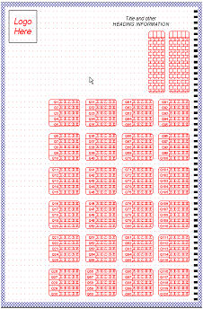
| Scanner using any channel as the
timing line |
|
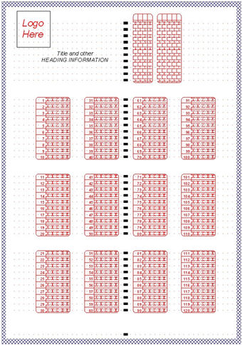
DRS and other scanners have the capacity to
use any channel as the "Clock Mark" (Timing Line) set. Below is the
form and the Grid window for a form of this type. A central timing line
prevents skew, particularly on lasers such as Xerox large scale
equipment where sheet travel is long edge first.
This company (TCG information Systems) has
used 102 timing lines per
A4 sheet, double sided, collecting 400 individual observations per
sheet successfully in huge application using a short distance from a
central timing line and an over-large response position.
|
|
| Top
|
| Saving the custom definition |
|
Once you have created custom timing line and
channel definitions compatible with your OMR, click Save As and type a
grid name to store the grid definition in the list available from the
Page setup dialog box.
Now that the design workspace is set up for your OMR, the first step in
creating an OMR form is to create the timing lines and set up the
response grid ready for OMR zones.
|
|
| Top
|
|
|
|